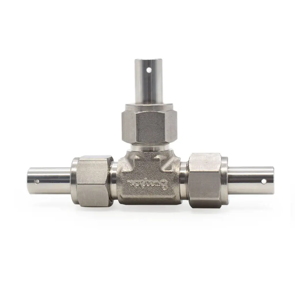
SS316 Battery Test Cell – 3-Electrode, 1/2″
No account required. Add the products you need, then send your request to our technical sales team.
Request Pricing AccessAlready have an approved account? Sign in
Reusable 1/2″ SS316 battery test cell for configurable three-electrode measurements
The S4R 1/2″ three-electrode battery test cell is a reusable laboratory platform built around a rigid SS316 stainless-steel body and three independently accessible metallic electrode contacts. The larger nominal 1/2″ working format supports electrodes up to Ø 12.7 mm, direct Ø 2.0 mm electrical connections and spring-assisted contact along the primary axial stack.
The enlarged working diameter provides additional active area and internal space while retaining the same fully disassemblable three-contact architecture. Because the body is electrically conductive, each metallic contact must remain isolated from it using the standard 0.05 mm PET/Mylar insulation films, supplied separately.
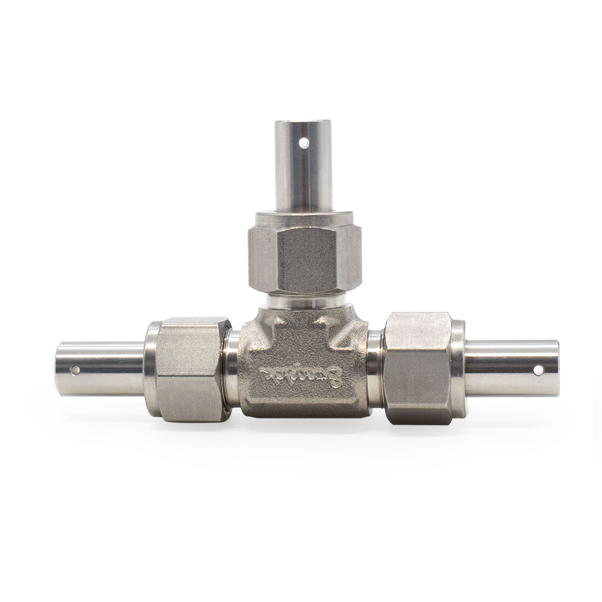
Designed for larger-format, configurable three-electrode experiments
A reusable 1/2″ stainless-steel platform combining a larger electrode format, three independent electrical interfaces, maintained axial stack contact and controlled electrical isolation.
Larger 1/2″ working format
Accommodates electrodes up to Ø 12.7 mm where a larger active area or internal working volume is required.
Maintained axial stack contact
An internal spring helps maintain mechanical and electrical contact across stacks up to 5 mm thick without implying a calibrated pressure.
Selectable contact materials
All three metallic contacts are available in SS316, aluminium or titanium according to the selected configuration and chemistry.
Three independent contacts
Three separately accessible metallic contacts allow the electrical function of each interface to be assigned according to the experimental protocol.
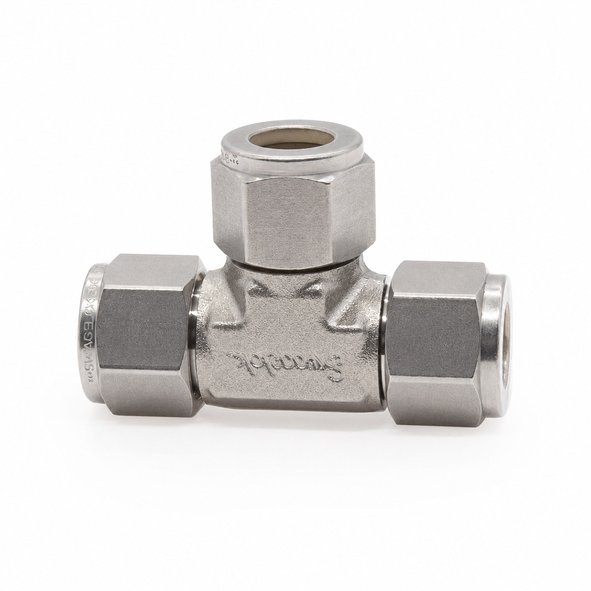
Rigid SS316 stainless-steel construction for repeated laboratory use
The cell incorporates a Swagelok® 316 stainless-steel three-port body component within an independently assembled S4R battery-test architecture. The metal body provides high mechanical rigidity, dimensional stability and a durable external structure for repeated assembly, disassembly and cleaning.
The nominal 1/2″ internal format provides a useful diameter of 12.7 mm and is specified for electrodes up to Ø 12.7 mm. The larger cross-section increases the available electrode area while preserving the same separable three-port architecture. Because the body is electrically conductive, correct isolation of all three metallic contacts from the body remains an essential part of the cell assembly.
Isolation of the three metallic contacts from the conductive body
The SS316 body is electrically conductive. Unintended metal-to-metal contact between any electrode contact and the body can create an electrical bypass and invalidate the intended measurement geometry. The standard S4R assembly therefore uses a thin insulating film between each metallic contact assembly and the stainless-steel body.
The specified film is 0.05 mm PET, commonly referred to as Mylar. It is supplied separately and should be installed intact, without folds, punctures or conductive bypass paths. Electrical isolation between each contact and the body should be verified before measurement.
PET / Mylar
Polyester electrical-insulation film used in the standard S4R assembly.
0.05 mm
Required with the standard metallic-contact configuration; not included.
Three independently accessible metallic contacts
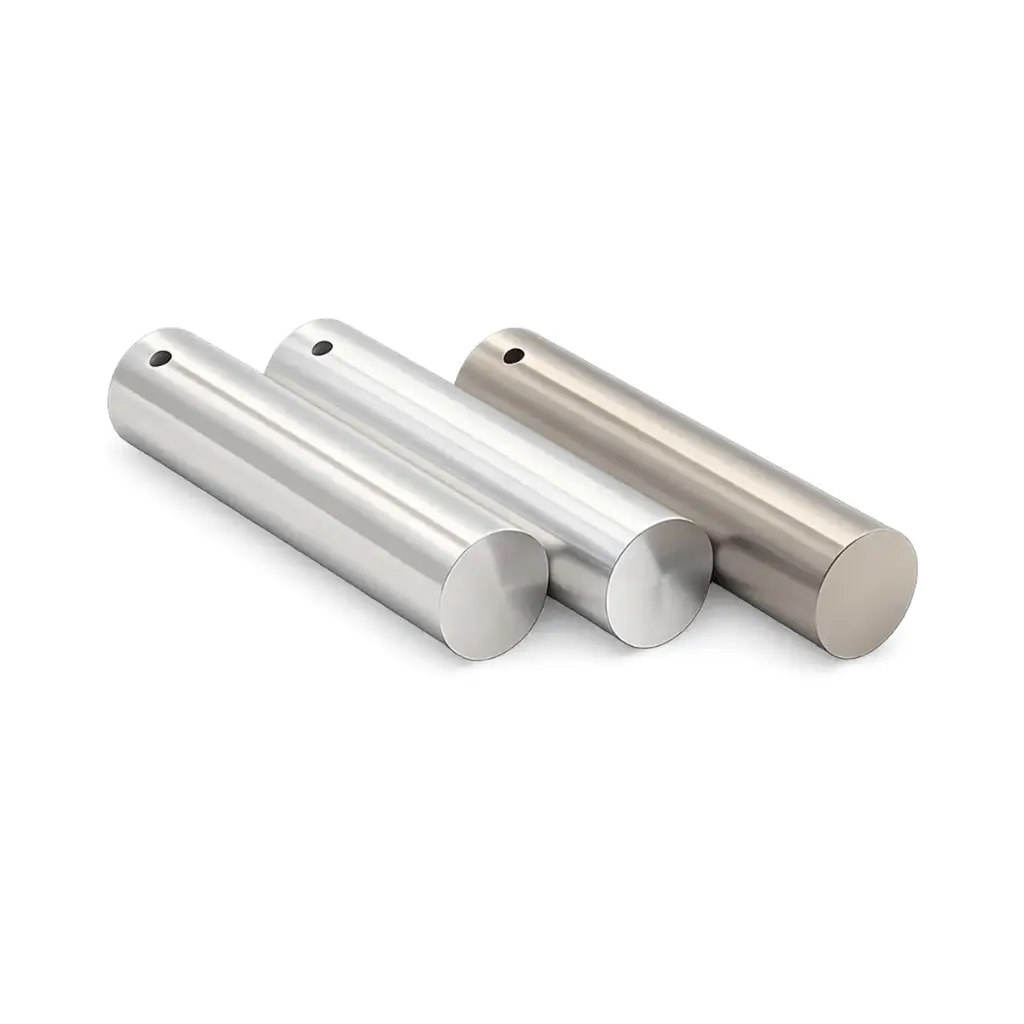
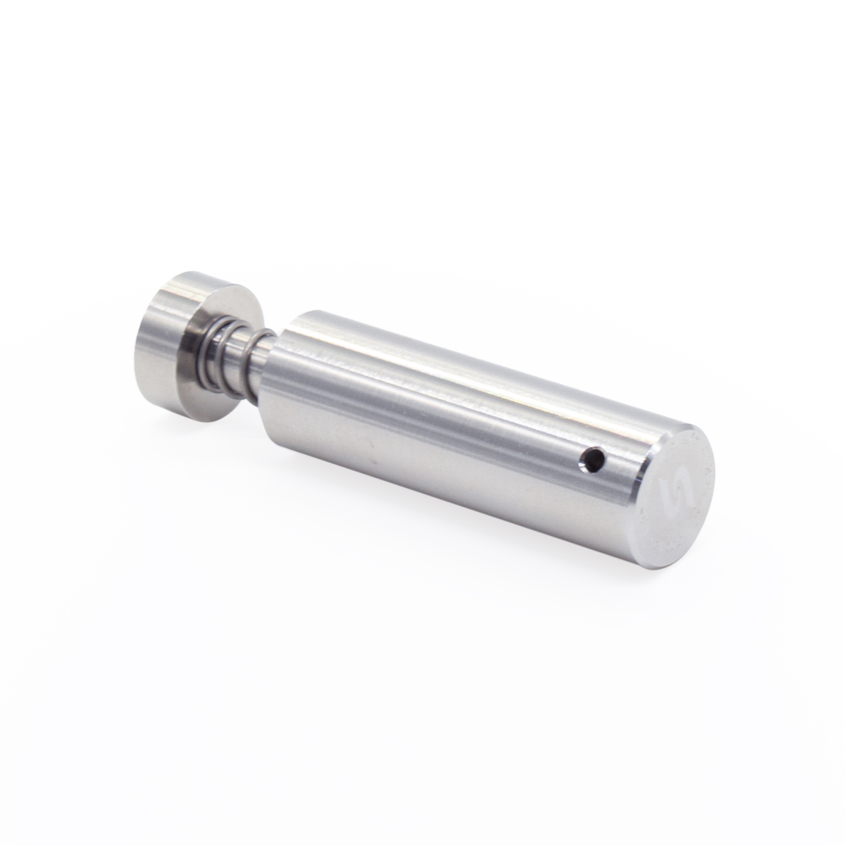
The cell provides three metallic electrode contacts. The two opposed plungers close the primary electrochemical stack and transmit the axial load generated by the spring assembly, while the third contact provides an additional independently wired interface outside the primary compression axis. All three contacts are supplied in the selected material family: SS316 stainless steel, aluminium or titanium.
Spring-assisted contact along the primary axial stack
The internal spring acts along the main cell axis and helps maintain mechanical and electrical contact between the two opposed electrode interfaces and the intervening stack as the assembly relaxes or changes dimension during testing. This reduces one source of variation in interfacial contact resistance.
Removable spacers set the working length of the axial assembly. Stack thicknesses up to 5 mm are supported in the validated configuration, while the third electrode contact remains independently positioned outside the primary compression axis.
SS316 compression nuts with PTFE ferrules
Each of the three ports uses a stainless-steel compression nut with a PTFE ferrule. Tightening the nut compresses the ferrule around the corresponding metallic contact, retaining its position and providing the local seal. The three ports remain accessible for adjustment, inspection and later disassembly.
Three independent electrical connections
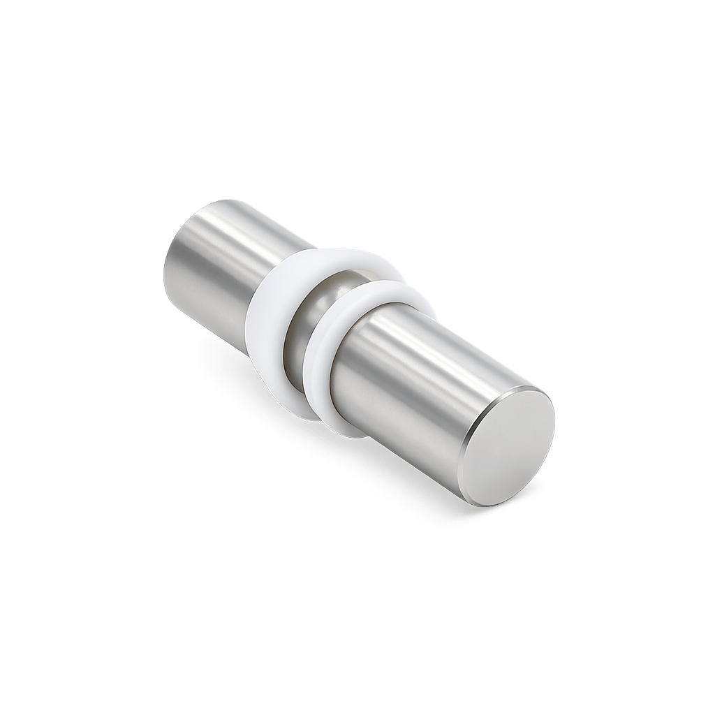
Each metallic contact contains a transverse Ø 2.0 mm connection port for standard 2 mm banana plugs. The three contacts can therefore be wired independently to the measurement instrument using conventional laboratory leads, with the electrical connections remaining outside the sealed cell volume.
The two opposed contacts define the main axial electrochemical stack. The third contact provides an additional independently wired electrode interface outside the primary compression axis. The mechanical hardware does not itself define which contact must serve a particular electrochemical function.
When operated in a conventional three-electrode configuration, the three electrical channels are assigned to working, counter and reference functions according to the electrode chemistry and experimental protocol. In that conventional arrangement, current is passed between the working and counter electrodes while the working-electrode potential is measured or controlled relative to the reference electrode.
A suitable reference electrode or reference-electrode material is not inherently provided by the cell hardware; it must be selected and implemented according to the specific electrochemical system under study.
Accessible assembly for repeated testing
The cell consists of a separable three-port stainless-steel body, three metallic contacts, three compression nuts, PTFE ferrules, the spring and spacer arrangement, and the required electrical-insulation films. Each experiment can therefore be opened after testing to recover electrodes, inspect interfaces and clean the internal surfaces.
Using the same body across a test series helps keep the principal hardware geometry constant while allowing contact material, stack arrangement and electrode chemistry to be adapted as required.
For related test architectures, the 1/4″ SS316 three-electrode battery test cell provides a more compact format, the 1/2″ SS316 two-electrode battery test cell provides the corresponding two-terminal geometry, and the 1/2″ PFA three-electrode battery test cell provides an electrically insulating PFA body alternative.
Reference dimensions
The original S4R technical drawing is retained to preserve the detailed geometry of the assembled three-electrode SS316 cell. The values below summarize the dimensions most relevant to installation and electrode selection.
Technical specifications
Reference data for the 1/2″ three-electrode SS316 battery test cell.
| Parameter | Specification |
|---|---|
| Cell type | Reusable SS316 battery test cell, three-electrode configuration |
| Electrode configuration | Three independently accessible metallic electrode contacts |
| Nominal format | 1/2″ |
| Useful internal diameter | 1/2″ (12.7 mm nominal) |
| Recommended max. electrode diameter | Ø 12.7 mm |
| Maximum stack thickness | 5 mm |
| Maximum validated temperature | 100 °C |
| Body material | 316 stainless-steel three-port body component (Swagelok®) |
| Compression nuts | 316 stainless steel |
| Ferrule material | PTFE |
| Contact materials | SS316, aluminium or titanium; all three contacts supplied in the selected material configuration |
| Required electrical insulation | 0.05 mm PET / Mylar film between each metallic contact assembly and conductive body; not included |
| Compression system | Internal spring with removable adjustment spacers acting along the primary axial stack; preload not calibrated |
| Electrical connection | Transverse Ø 2.0 mm port on each metallic contact for standard 2 mm banana plugs |
| Conventional three-electrode use | Working, counter and reference functions assigned according to the experimental protocol; suitable reference-electrode system selected separately |
| Overall assembled length | 114 mm |
| Overall assembled height | 66 mm |
| Body dimension shown on drawing | 25 mm |
| End diameter shown on drawing | Ø 12.6 mm |
| Approximate mass | 230 g |
| Construction | Fully disassemblable and reusable for sample loading, electrode recovery, cleaning and reconfiguration |
| Typical applications | Battery-material studies, supercapacitor research and electrochemical experiments requiring three independently connected electrode interfaces |
Included components
Supplied as a complete reusable 1/2″ three-contact assembly according to the selected contact-material configuration.
Selecting and operating the 1/2″ SS316 three-electrode configuration
Why are insulation films required?
The stainless-steel body is electrically conductive, so each metallic contact must remain isolated from it. The standard S4R assembly uses 0.05 mm PET/Mylar films, supplied separately, and isolation should be checked before measurement.
What is the maximum recommended electrode diameter?
The nominal internal format is 1/2″ (12.7 mm). The recommended maximum electrode diameter for this configuration is Ø 12.7 mm.
How is the third contact used?
It provides an additional independently wired electrode interface. In a conventional three-electrode experiment, the three channels are assigned to working, counter and reference functions according to the chemistry and protocol; the hardware does not impose those roles.
Is a reference electrode included?
No dedicated reference-electrode system is included. When a conventional three-electrode measurement is required, the appropriate reference electrode or reference-electrode material must be selected for the electrolyte and experimental protocol.
Is the stack pressure defined?
No calibrated pressure value is specified. The internal spring maintains axial contact across the primary stack, while spacers set the working length for the 1/2″ format. The cell is not intended as a calibrated pressure fixture.
Which contact materials are available?
SS316, aluminium and titanium are available. All three metallic contacts are supplied in the selected material configuration, and compatibility should be assessed for the electrolyte, potential window and temperature used.
Before use
Electrical isolation
Verify that all three metallic contacts are electrically isolated from the conductive SS316 body before measurement. A damaged, displaced or bypassed insulation film can create an unintended electrical path.
Material compatibility
Compatibility between the electrolyte, SS316 body, PTFE ferrules, PET/Mylar insulation and selected contact material should be assessed for solvent, salt, concentration, temperature and potential window.
Operating and maintenance
The maximum validated temperature for the complete cell assembly is 100 °C. Ferrules, sealing surfaces, insulation films and metallic contacts should be inspected and cleaned using procedures compatible with the materials and chemistry used.
Reusable 1/2″ SS316 battery test cell for configurable three-electrode measurements
The S4R 1/2″ three-electrode battery test cell is a reusable laboratory platform built around a rigid SS316 stainless-steel body and three independently accessible metallic electrode contacts. The larger nominal 1/2″ working format supports electrodes up to Ø 12.7 mm, direct Ø 2.0 mm electrical connections and spring-assisted contact along the primary axial stack.
The enlarged working diameter provides additional active area and internal space while retaining the same fully disassemblable three-contact architecture. Because the body is electrically conductive, each metallic contact must remain isolated from it using the standard 0.05 mm PET/Mylar insulation films, supplied separately.
Designed for larger-format, configurable three-electrode experiments
A reusable 1/2″ stainless-steel platform combining a larger electrode format, three independent electrical interfaces, maintained axial stack contact and controlled electrical isolation.
Larger 1/2″ working format
Accommodates electrodes up to Ø 12.7 mm where a larger active area or internal working volume is required.
Maintained axial stack contact
An internal spring helps maintain mechanical and electrical contact across stacks up to 5 mm thick without implying a calibrated pressure.
Selectable contact materials
All three metallic contacts are available in SS316, aluminium or titanium according to the selected configuration and chemistry.
Three independent contacts
Three separately accessible metallic contacts allow the electrical function of each interface to be assigned according to the experimental protocol.
Rigid SS316 stainless-steel construction for repeated laboratory use
The cell incorporates a Swagelok® 316 stainless-steel three-port body component within an independently assembled S4R battery-test architecture. The metal body provides high mechanical rigidity, dimensional stability and a durable external structure for repeated assembly, disassembly and cleaning.
The nominal 1/2″ internal format provides a useful diameter of 12.7 mm and is specified for electrodes up to Ø 12.7 mm. The larger cross-section increases the available electrode area while preserving the same separable three-port architecture. Because the body is electrically conductive, correct isolation of all three metallic contacts from the body remains an essential part of the cell assembly.
Isolation of the three metallic contacts from the conductive body
The SS316 body is electrically conductive. Unintended metal-to-metal contact between any electrode contact and the body can create an electrical bypass and invalidate the intended measurement geometry. The standard S4R assembly therefore uses a thin insulating film between each metallic contact assembly and the stainless-steel body.
The specified film is 0.05 mm PET, commonly referred to as Mylar. It is supplied separately and should be installed intact, without folds, punctures or conductive bypass paths. Electrical isolation between each contact and the body should be verified before measurement.
PET / Mylar
Polyester electrical-insulation film used in the standard S4R assembly.
0.05 mm
Required with the standard metallic-contact configuration; not included.
Three independently accessible metallic contacts
The cell provides three metallic electrode contacts. The two opposed plungers close the primary electrochemical stack and transmit the axial load generated by the spring assembly, while the third contact provides an additional independently wired interface outside the primary compression axis. All three contacts are supplied in the selected material family: SS316 stainless steel, aluminium or titanium.
Spring-assisted contact along the primary axial stack
The internal spring acts along the main cell axis and helps maintain mechanical and electrical contact between the two opposed electrode interfaces and the intervening stack as the assembly relaxes or changes dimension during testing. This reduces one source of variation in interfacial contact resistance.
Removable spacers set the working length of the axial assembly. Stack thicknesses up to 5 mm are supported in the validated configuration, while the third electrode contact remains independently positioned outside the primary compression axis.
SS316 compression nuts with PTFE ferrules
Each of the three ports uses a stainless-steel compression nut with a PTFE ferrule. Tightening the nut compresses the ferrule around the corresponding metallic contact, retaining its position and providing the local seal. The three ports remain accessible for adjustment, inspection and later disassembly.
Three independent electrical connections
Each metallic contact contains a transverse Ø 2.0 mm connection port for standard 2 mm banana plugs. The three contacts can therefore be wired independently to the measurement instrument using conventional laboratory leads, with the electrical connections remaining outside the sealed cell volume.
The two opposed contacts define the main axial electrochemical stack. The third contact provides an additional independently wired electrode interface outside the primary compression axis. The mechanical hardware does not itself define which contact must serve a particular electrochemical function.
When operated in a conventional three-electrode configuration, the three electrical channels are assigned to working, counter and reference functions according to the electrode chemistry and experimental protocol. In that conventional arrangement, current is passed between the working and counter electrodes while the working-electrode potential is measured or controlled relative to the reference electrode.
A suitable reference electrode or reference-electrode material is not inherently provided by the cell hardware; it must be selected and implemented according to the specific electrochemical system under study.
Accessible assembly for repeated testing
The cell consists of a separable three-port stainless-steel body, three metallic contacts, three compression nuts, PTFE ferrules, the spring and spacer arrangement, and the required electrical-insulation films. Each experiment can therefore be opened after testing to recover electrodes, inspect interfaces and clean the internal surfaces.
Using the same body across a test series helps keep the principal hardware geometry constant while allowing contact material, stack arrangement and electrode chemistry to be adapted as required.
For related test architectures, the 1/4″ SS316 three-electrode battery test cell provides a more compact format, the 1/2″ SS316 two-electrode battery test cell provides the corresponding two-terminal geometry, and the 1/2″ PFA three-electrode battery test cell provides an electrically insulating PFA body alternative.
Reference dimensions
The original S4R technical drawing is retained to preserve the detailed geometry of the assembled three-electrode SS316 cell. The values below summarize the dimensions most relevant to installation and electrode selection.
Technical specifications
Reference data for the 1/2″ three-electrode SS316 battery test cell.
| Parameter | Specification |
|---|---|
| Cell type | Reusable SS316 battery test cell, three-electrode configuration |
| Electrode configuration | Three independently accessible metallic electrode contacts |
| Nominal format | 1/2″ |
| Useful internal diameter | 1/2″ (12.7 mm nominal) |
| Recommended max. electrode diameter | Ø 12.7 mm |
| Maximum stack thickness | 5 mm |
| Maximum validated temperature | 100 °C |
| Body material | 316 stainless-steel three-port body component (Swagelok®) |
| Compression nuts | 316 stainless steel |
| Ferrule material | PTFE |
| Contact materials | SS316, aluminium or titanium; all three contacts supplied in the selected material configuration |
| Required electrical insulation | 0.05 mm PET / Mylar film between each metallic contact assembly and conductive body; not included |
| Compression system | Internal spring with removable adjustment spacers acting along the primary axial stack; preload not calibrated |
| Electrical connection | Transverse Ø 2.0 mm port on each metallic contact for standard 2 mm banana plugs |
| Conventional three-electrode use | Working, counter and reference functions assigned according to the experimental protocol; suitable reference-electrode system selected separately |
| Overall assembled length | 114 mm |
| Overall assembled height | 66 mm |
| Body dimension shown on drawing | 25 mm |
| End diameter shown on drawing | Ø 12.6 mm |
| Approximate mass | 230 g |
| Construction | Fully disassemblable and reusable for sample loading, electrode recovery, cleaning and reconfiguration |
| Typical applications | Battery-material studies, supercapacitor research and electrochemical experiments requiring three independently connected electrode interfaces |
Included components
Supplied as a complete reusable 1/2″ three-contact assembly according to the selected contact-material configuration.
Selecting and operating the 1/2″ SS316 three-electrode configuration
Why are insulation films required?
The stainless-steel body is electrically conductive, so each metallic contact must remain isolated from it. The standard S4R assembly uses 0.05 mm PET/Mylar films, supplied separately, and isolation should be checked before measurement.
What is the maximum recommended electrode diameter?
The nominal internal format is 1/2″ (12.7 mm). The recommended maximum electrode diameter for this configuration is Ø 12.7 mm.
How is the third contact used?
It provides an additional independently wired electrode interface. In a conventional three-electrode experiment, the three channels are assigned to working, counter and reference functions according to the chemistry and protocol; the hardware does not impose those roles.
Is a reference electrode included?
No dedicated reference-electrode system is included. When a conventional three-electrode measurement is required, the appropriate reference electrode or reference-electrode material must be selected for the electrolyte and experimental protocol.
Is the stack pressure defined?
No calibrated pressure value is specified. The internal spring maintains axial contact across the primary stack, while spacers set the working length for the 1/2″ format. The cell is not intended as a calibrated pressure fixture.
Which contact materials are available?
SS316, aluminium and titanium are available. All three metallic contacts are supplied in the selected material configuration, and compatibility should be assessed for the electrolyte, potential window and temperature used.
Before use
Electrical isolation
Verify that all three metallic contacts are electrically isolated from the conductive SS316 body before measurement. A damaged, displaced or bypassed insulation film can create an unintended electrical path.
Material compatibility
Compatibility between the electrolyte, SS316 body, PTFE ferrules, PET/Mylar insulation and selected contact material should be assessed for solvent, salt, concentration, temperature and potential window.
Operating and maintenance
The maximum validated temperature for the complete cell assembly is 100 °C. Ferrules, sealing surfaces, insulation films and metallic contacts should be inspected and cleaned using procedures compatible with the materials and chemistry used.
Our latest content
Check out what's new in our company !